จำนวน Repository ( 14 )

การพัฒนาโปรแกรมจำลองค่าพารามิเตอร์สายส่งความถี่สูงโดยใช้ Matlab/Simulink
มีวัตถุประสงค์ 1) เพื่อพัฒนาโปรแกรมจาลองค่าพารามิเตอร์สายส่งความถี่สูงโดยใช้ Matlab/Simulink 2) เพื่อหาประสิทธิภาพโปรแกรมจาลองค่าพารามิเตอร์สายส่งความถี่สูงโดยใช้ Matlab/ Simulink และ 3) เพื่อเปรียบเทียบผลการคานวณจากโปรแกรมที่พัฒนาขึ้นกับผลจากการคิดคานวณ ค่าพารามิเตอร์สายส่งความถี่สูงที่นามาพัฒนาเป็นโปรแกรมนั้น แบ่งตามประเภทของสายส่งในอากาศซึ่งขึ้นอยู่กับความถี่และการใช้งาน ได้แก่ สายส่งสัญญาณแบบสองสาย สายส่งสัญญาณแบบระนาบคู่ และสายส่งสัญญาณแบบโคแอกซ์ ส่วนประกอบของโปรแกรม แบ่งเป็น 3 หน้าจอ ได้แก่ หน้าจอหลัก หน้าจอแสดงโปรแกรมหลัก และหน้าจอคานวณค่าพารามิเตอร์ การตรวจสอบหาคุณภาพและประสิทธิภาพของระบบโดยผู้เชี่ยวชาญจานวน 5 ท่านที่มีความเชี่ยวชาญเฉพาะทาง เครื่องมือที่ใช้ในการวิจัย ได้แก่ แบบประเมินการตรวจสอบคุณภาพ แบ่งออกเป็น 2 ส่วน คือ ส่วนที่ 1 การทดสอบโปรแกรม และส่วนที่ 2 การทดสอบระบบ สถิติที่ใช้ในการวิเคราะห์ข้อมูล ได้แก่ ค่าเฉลี่ย ค่าร้อยละ และส่วนเบี่ยงเบนมาตรฐาน ผลการวิจัยพบว่า 1. ผลการพัฒนาโปรแกรมจาลองค่าพารามิเตอร์สายส่งความถี่สูงโดยใช้ Matlab/Simulink มีโครงสร้างของการออกแบบโปรแกรม แบ่งการทางานออกเป็น 3 ส่วนหลัก ๆ ได้แก่ ส่วนการคานวณโปรแกรมสายส่งสัญญาณสองสาย ส่วนการคานวณโปรแกรมสายส่งสัญญาณระนาบคู่ และส่วนการคานวณโปรแกรมสายส่งสัญญาณโคแอกซ์ ซึ่งในการคานวณโปรแกรมแต่ละส่วนมีหลักการทางานของโปรแกรม ซึ่งการคานวณโปรแกรมแต่ละส่วนมีหลักการทางานของโปรแกรม แบ่งออกเป็น กาหนดเงื่อนไขของขอบเขตของสายส่ง คานวณค่าความจุ คานวณค่าความนา คานวณค่าความเหนี่ยวนา คานวณค่าความต้านทาน และคานวณค่าอิมพีแดนซ์ ซึ่งการคานวณทุกส่วนสามารถแสดงผลการคานวณ เลือกการคานวณสายส่งสัญญาณแบบต่าง ๆ ซึ่งโปรแกรมที่คณะผู้วิจัยทาการพัฒนานี้ แบ่งสายส่งสัญญาณตามประเภทการใช้งานและความถี่ จานวน 3 สายส่งสัญญาณ ได้แก่ สายส่งสัญญาณแบบสองสาย สายส่งสัญญาณแบบระนาบคู่ และสายส่งสัญญาณแบบโคแอกซ์ 2. ผลการหาประสิทธิภาพโปรแกรมจาลองค่าพารามิเตอร์สายส่งความถี่สูงโดยใช้ Matlab/ Simulink แบ่งออกเป็น 2 ส่วน พบว่า ส่วนที่ 1 ผลการทดสอบความถูกต้องทางด้านภาษาคาสั่งและความสามารถในการทางาน ส่วนย่อยทั้ง 5 กระบวนการทางาน มีความถูกต้อง ไม่มีข้อผิดพลาดในกระบวนการ ซึ่งกระบวนการทางานแต่ละกระบวนการทางานมีความเชื่อมโยงกันตามที่ได้ออกแบบไว้ โดยภาพรวมการพัฒนาระบบสามารถทางานได้ไม่เกิดข้อผิดพลาด และเมื่อทาการประเมินการยอมรับระบบ พบว่าโปรแกรมที่พัฒนาขึ้นสามารถนาไปใช้เป็นเครื่องมือวิจัยได้ เมื่อพิจารณาเป็นรายด้านพบว่า ด้านการออกแบบ เรื่องมาตรฐานการออกแบบ คุณภาพการออกแบบ และโครงสร้างที่ออกแบบไม่ซับซ้อนเป็นที่ยอมรับ ข จากผู้เชี่ยวชาญ คิดเป็นเปอร์เซ็นต์อยู่ระหว่าง 80% - 83% ด้านกระบวนการทางานเรื่องการเรียงลาดับกระบวนการทางาน การเข้าใจในภาษาที่ใช้ในการทางานเป็นที่ยอมรับจากผู้เชี่ยวชาญ คิดเป็นเปอร์เซ็นต์อยู่ระหว่าง 84% - 80% และด้านหน้าที่การทางานเรื่องวิธีการทางานในแต่ละการทางาน ความสอดคล้องกับความต้องการของผู้ใช้งานเป็นที่ยอมรับจากผู้เชี่ยวชาญ คิดเป็นเปอร์เซ็นต์อยู่ระหว่าง 89% - 79% และส่วนที่ 2 การหาประสิทธิภาพการทางานของโปรแกรมจาลองค่าพารามิเตอร์สายส่งความถี่สูงโดยใช้ Matlab/Simulink ที่พัฒนาขึ้น พบว่า โปรแกรมจาลองที่พัฒนาขึ้นมีประสิทธิภาพการทางานอยู่ในระดับมาก (𝑥̅=4.04𝑆.𝐷.=0.36) 3. ผลการเปรียบเทียบระหว่างผลการคานวณจากโปรแกรมที่พัฒนาขึ้นกับผลจากการคิดคานวณ มีผลการคานวณที่ตรงกัน จึงแสดงให้เห็นว่า โปรแกรมที่พัฒนาขึ้นสามารถนาไปใช้แทนการคานวณด้วยมือได้อย่างมีประสิทธิภาพ
Compensation of low frequency oscillation on power system using flexible ac transmission systems devices
This paper presents a study of low-frequency oscillations in compensated electric power systems with Flexible AC Transmission System of the power system frequency using PSAT Tool box To assist in the analysis of the stability of the system When the power transients in power systems is simulated By using standard IEEE 14 bus system as a case study. The Equipment that used to control the swing frequency of the is a flexible electrical power control devices or FACTS are two kinds of serial and parallel. The analysis showed that two models are compared with the time (Time Domain) and see the effect of the Eigen (Eigen Value) of the simulation results show work to see that controls are electrical flexible compensation. of low frequency oscillations in power systems in acceptable coordinates
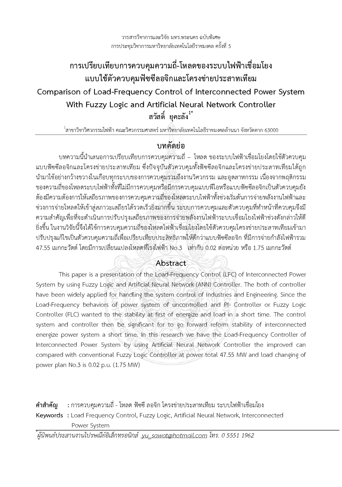
Comparison of load-frequency control of interconnected power system with fuzzy logic and artificial neural Network controller
This paper is a presentation of the Load-Frequency Control (LFC) of Interconnected Power System by using Fuzzy Logic and Artificial Neural Network (ANN) Controller. The both of controller have been widely applied for handling the system control of Industries and Engineering. Since the Load-Frequency behaviors of power system of uncontrolled and PI- Controller or Fuzzy Logic Controller (FLC) wanted to the stability at first of energize and load in a short time. The control system and controller then be significant for to go forward reform stability of interconnected energize power system a short time. In this research we have the Load-Frequency Controller of Interconnected Power System by using Artificial Neural Network Controller the improved can compared with conventional Fuzzy Logic Controller at power total 47.55 MW and load changing of power plan No.3 is 0.02 p.u. (1.75 MW)
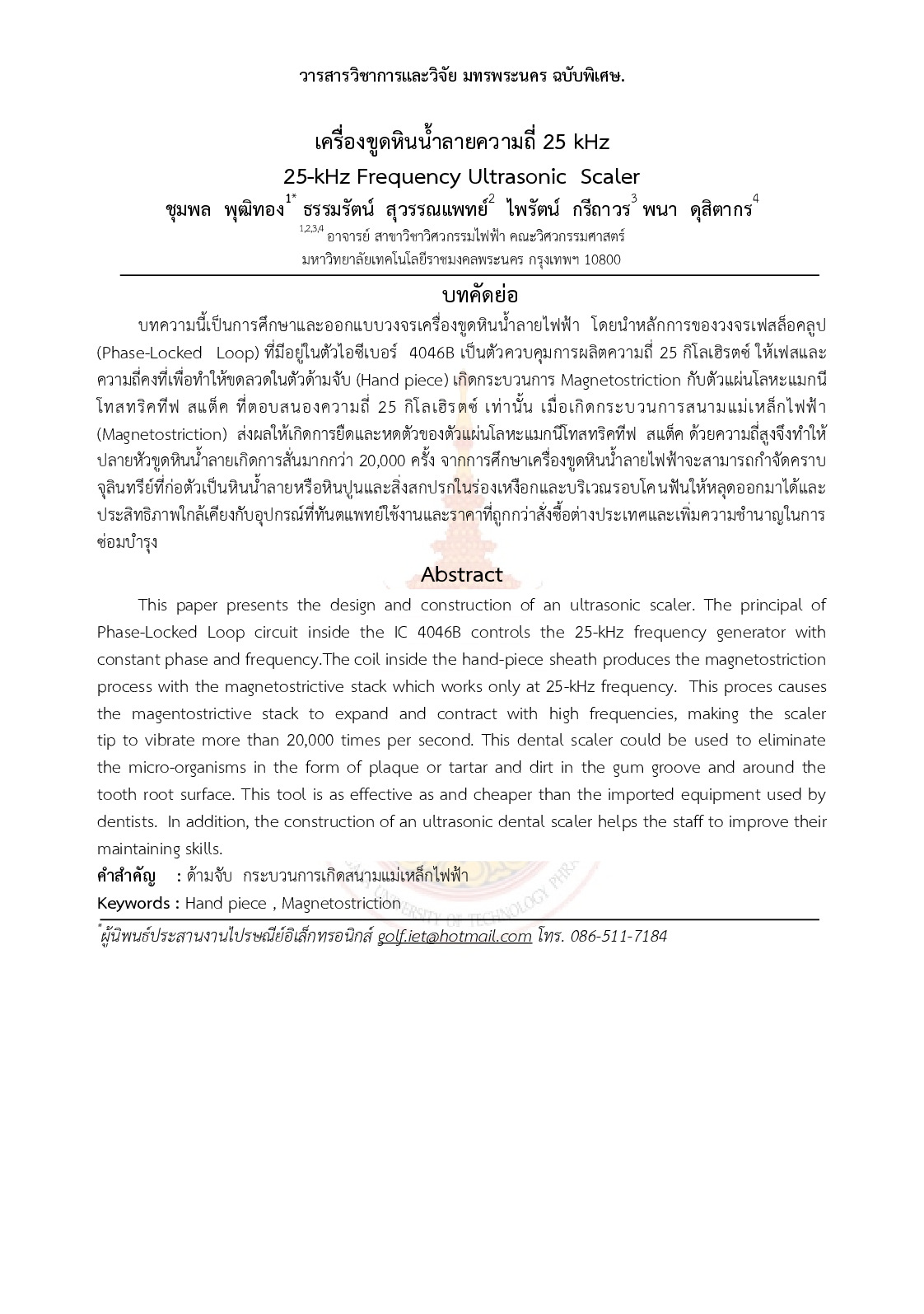
25-kHz Frequency Ultrasonic Scaler
This paper presents the design and construction of an ultrasonic scaler. The principal of Phase-Locked Loop circuit inside the IC 4046B controls the 25-kHz frequency generator with constant phase and frequency.The coil inside the hand-piece sheath produces the magnetostriction process with the magnetostrictive stack which works only at 25-kHz frequency. This proces causes the magentostrictive stack to expand and contract with high frequencies making the scaler tip to vibrate more than 20000 times per second. This dental scaler could be used to eliminate the micro-organisms in the form of plaque or tartar and dirt in the gum groove and around the tooth root surface. This tool is as effective as and cheaper than the imported equipment used by dentists. In addition the construction of an ultrasonic dental scaler helps the staff to improve their maintaining skills.

Design and Construction High Voltage,High Frequency Transformer Rated 500 kV 250 kHz
This project design and constructions high voltage high frequency transformer or tesla transformer. The tesla transformer is design at 500 kV rating voltage and 250 kHz resonant frequency. By coupling air axle and have the air are the electric insulator between primary coil and secondary coil Which primary coil test at 60 degree Group part spark gap is will the Electrostatic gap. This paper propose and consider high voltage high frequency transformer at 500 kV and 250 kHz rated. For use a transformer aforementioned is the equipment for test flash over prenouaena of porcelain insulator and electric insulation.